
Copper–aluminium plate · Layer structure guide
Choose the metals needed on the two working faces, then specify each layer separately.
A single-sided copper-aluminium clad plate has copper on one broad face and aluminium on the other. A double-sided copper-clad aluminium plate has copper on both broad faces around an aluminium core. The difference is where the copper sits—not simply how much copper the plate contains. EMS describes both constructions in its copper-clad aluminium literature. [1]
For OEM buyers and fabricators, the useful starting point is the assembly: which face must be copper, which must be aluminium, and what will happen to each face during machining?
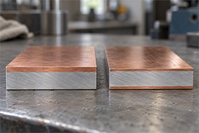
1. Single-sided and double-sided: see the difference
This guide covers bonded, all-metal copper–aluminium material. It does not describe an insulated circuit-board laminate. Here, “double-sided” means copper on the two broad faces; it does not mean that copper wraps around every edge.
Original teaching example: compare two uncoated plates with the same nominal 4.00 mm total thickness at delivery. Both have full-face cladding and no copper edge wrap. The dimensions below explain layer placement; they are not stock specifications or recommended designs.
Single-sided · Cu / Al
Face A: copper · 0.60 mm
3.40 mm
Face B: aluminium surface
0.60 + 3.40 = 4.00 mm
Double-sided · Cu / Al / Cu
Face A: copper · 0.30 mm
3.40 mm
Face B: copper · 0.30 mm
0.30 + 3.40 + 0.30 = 4.00 mm
Do not assume every double-sided product has equal copper layers. Write the required thickness for Face A and Face B individually, even when the values are identical. Confirm the proposed construction against the supplier’s current product data.
2. Start with a simple face map
Mark Face A and Face B on the drawing, then state what each face must do. c:met’s CUPAL technical information describes copper–aluminium clad material as a transition element between copper and aluminium conductors. This makes the required metal at each mating face an important purchasing input. [2]
The table below is a requirements check, not an electrical connection design. The assembly designer must define the suitable contact materials and joint requirements.
On a phone, swipe the table sideways to view all columns.
| Required working faces | Construction to review | Drawing note to add |
|---|---|---|
| Copper on A; aluminium on B | Single-sided Cu / Al | Identify both faces and the installed orientation. |
| Copper on A and B | Double-sided Cu / Al / Cu | State copper thickness and required coverage on each face. |
| Different contact and machining areas on one face | Review a face layout as well as the cross-section. | Mark contact pads, pockets and areas where copper must remain. |
Use an assembly reference such as “Face A towards the copper contact” instead of “copper on top”. Top and bottom can change when a loose plate is turned over. Tie the face labels to a drawing view or an agreed identification method.
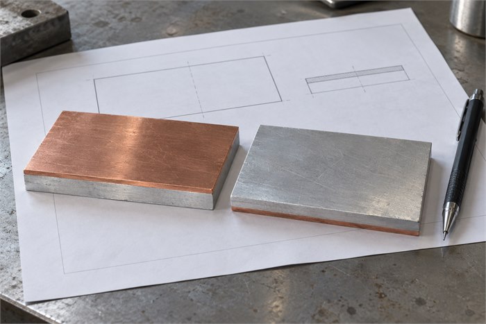
3. Check what remains after cutting and machining
Milled faces and pockets
Removing material from a copper face also reduces the copper layer there. In an ideal nominal example, removing 0.20 mm from a 0.30 mm copper layer leaves 0.10 mm, before allowing for thickness and machining variation.
Specify the copper needed on the finished contact area and discuss the incoming allowance. Total finished thickness alone does not establish the copper remaining on either face.
Cut edges and drilled holes
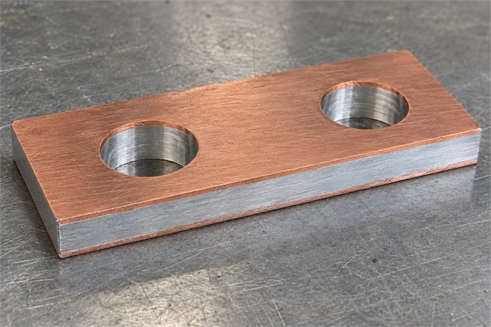
In the full-face constructions shown above, a through-hole or a cut edge exposes the layer sequence, including aluminium. Copper on both broad faces does not make the hole wall or edge solid copper.
Show any edge treatment, coating or hole-contact requirement separately. Agree deburring and inspection criteria rather than assuming the word “double-sided” covers these features.
If the plate will be bent or joined, tell the supplier which face is involved and describe the planned process. The layer arrangement alone does not establish an acceptable bend radius, joining temperature or finished bond quality.
4. Turn the face map into an enquiry
Confirm that the required delivery form is plate or sheet rather than another item in the copper–aluminium product range. Include the drawing revision, plate width and length, quantity and intended use.
Example enquiry: double-sided plate
“Please review the attached drawing for a copper / aluminium / copper plate. Proposed nominal layers at delivery: Face A copper 0.30 mm / aluminium core 3.40 mm / Face B copper 0.30 mm; total 4.00 mm. Copper is required over both full broad faces; no edge wrap is specified. No face machining is planned.
Please identify the proposed material grades and condition, achievable layer and total-thickness tolerances, face identification method and inspection documents. State the proposed layer measurement and bond inspection methods with acceptance criteria for approval. List any alternative construction separately.”
The numbers are fictional enquiry inputs. Replace them with the project requirements and obtain confirmation of feasibility. For a machined part, add the processing areas and the copper required afterwards; identify which party supplies the final inspected component.
Frequently asked questions
Is double-sided always the better option?
No. A copper surface on each side is useful only when it matches the design. If one working face must remain aluminium, a double-sided copper construction changes that interface and needs a design review.
Can a single-sided plate simply be installed either way up?
Only if the assembly design permits it. Reversing the plate swaps the exposed metals. Keep face identification consistent through cutting, packing and installation, especially when the finished shape does not make orientation obvious.
Does the layer drawing prove the plate is well bonded?
No. A section drawing defines the intended construction. Bond quality requires separate inspection or test evidence linked to the supplied material and agreed acceptance criteria. Do not infer current rating or service life from the layer count.
Send a face-labelled drawing with your enquiry
Use the enquiry form on the copper-clad aluminium plate and sheet page. Include the layer order, per-face copper requirement, overall dimensions, quantity and planned processing so the proposed construction can be discussed against the same specification.
Sources and further reading
[1] Engineered Materials Solutions: Copper Clad Aluminum, pages 2–3, particularly “Ratio”. Describes copper on one or both sides of aluminium. Its published constructions are technical references, not a statement of this website’s current supply range.
[2] c:met GmbH: CUPAL product and technical information, introduction and manufacturing description. Describes copper-clad aluminium and its use as a transition material between copper and aluminium conductors. The examples in this article are independent teaching models.